
How to Calculate Spring Tension for Cordless Window Blinds
An OEM engineering workflow to translate blind weight into target lift force, torque band, and preload turns—so the blind feels smooth, holds position, and doesn’t slam.
 |
Quick Summary
“Spring tension” in cordless blinds usually means spring output + preload that balances the blind’s gravity.
The practical target is: spring lift force ≈ (blind weight × 1.10), then tuned so the user pull force stays ≤ 30 N,
rise time is 8–15 s for a full stroke, and mid-height drift is near-zero.
This guide gives the step-by-step calculation, a numeric example, and an OEM validation table you can copy into QC.
Contents
- Define “spring tension” (force vs torque)
- Inputs you must measure (minimum set)
- Step 1 — Convert blind weight to target lift force
- Step 2 — Convert lift force to required torque band
- Step 3 — Convert torque band to preload turns (factory tuning)
- Worked example (with real numbers)
- OEM validation checklist + data table
- Troubleshooting: drift, slam, squeak, chatter
- FAQ
1) Define “Spring Tension” in Cordless Blinds
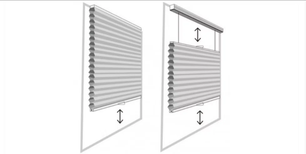
In cordless window blinds, the word “tension” is used loosely. Engineers usually need two quantities:
 |
- Lift force (N): the upward force the spring system provides to offset gravity.
- Torque (N·m): the twisting moment at the tube/drum that creates lift force.
Most OEM mistakes come from mixing these up. Your design target should be defined in force (user feel + balance),
then translated into torque (module selection + preload turns).
2) Inputs You Must Measure (Minimum Set)
If you can’t measure these, you’re not “engineering” yet—you’re doing vibes. (Vibes do not pass QC.)
| Input | Symbol | Units | How to get it (fast) |
|---|---|---|---|
| Blind width | W | m | Finished width (fabric cut width if known) |
| Blind drop (height) | H | m | Max extension |
| Fabric mass per area | ρA | kg/m² | Supplier datasheet (or weigh a known area) |
| Bottom rail + end parts mass | mrail | kg | Weigh one assembled rail |
| Tube outside diameter | D | m | Typically Ø32 / Ø38 mm class |
| Friction / efficiency factor | kfr | — | Start with 1.10 if you have no test data |
3) Step 1 — Convert Blind Weight to Target Lift Force
First calculate total mass:
mtotal = (ρA × W × H) + mrail
Convert to weight (force):
G = mtotal × 9.8 (N)
Add friction/drag allowance:
Geff = G × kfr
where kfr is usually 1.05–1.15 for well-built systems.
Set your target spring lift force band:
Ftarget = Geff × (1.05 to 1.10)
If you push higher (e.g., +15%+), you’ll get “fast snap-up,” higher pull-down force, louder end impacts,
and more customer complaints than you saved in “strong lift.”
4) Step 2 — Convert Lift Force to Required Torque Band
Lift force turns into torque through an effective radius:
Treq = Ftarget × reff
For most cordless roller blind architectures, a useful first approximation is:
reff ≈ D/2.
(Fabric build-up changes radius slightly; if you want higher accuracy, use average radius between fully rolled and fully unrolled.)
| Tube class | D (mm) | reff (m) | Torque rule of thumb |
|---|---|---|---|
| Ø32 | 32 | 0.016 | T(N·m) ≈ 0.016 × F(N) |
| Ø38 | 38 | 0.019 | T(N·m) ≈ 0.019 × F(N) |
5) Step 3 — Convert Torque Band to Preload Turns (Factory Tuning)
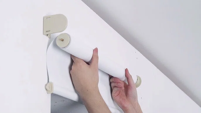
In production, preload is your “knob.” The practical goal is not a perfect equation—it’s a repeatable
tuning method that lands you in the same feel band every time.
 |
5.1 A Repeatable Preload Workflow (Works for Most Cordless Platforms)
- Pick a spring module whose rated torque band covers Treq with margin (don’t run at the cliff edge).
- Start preload at a conservative factory default (example: +3 turns from “zero slack”).
- Run 3 cycles to “settle” interfaces (friction bedding).
- Measure:
- Pull-down force at 25% / 50% / 75% drop
- Rise time from full drop to top
- Mid-height drift (hold at 50% for 60 s)
- Adjust preload in 0.5-turn increments until you meet acceptance limits (see Section 7).
5.2 What “Good” Looks Like (User-Feel Targets)
- Downward pull force: ≤ 30 N (premium feel often targets 12–22 N)
- Full rise time: 8–15 s (too fast = slam risk; too slow = “stuck” perception)
- Mid-height drift: ≈ 0 (practical spec: < 10 mm/min)
- Noise: controlled by damping + interfaces; avoid “knock” at top stop
6) Worked Example (Numbers You Can Audit)
Assume: Cordless roller blind, W = 1.0 m, H = 2.0 m, fabric ρA = 1.2 kg/m², bottom rail mass = 0.8 kg, tube = Ø38, friction factor kfr = 1.10.
| Step | Calculation | Result |
|---|---|---|
| Fabric mass | mfab = ρA × W × H = 1.2 × 1.0 × 2.0 | 2.4 kg |
| Total mass | mtotal = 2.4 + 0.8 | 3.2 kg |
| Weight force | G = 3.2 × 9.8 | 31.4 N |
| Effective load | Geff = 31.4 × 1.10 | 34.5 N |
| Target force band | Ftarget = 34.5 × (1.05 to 1.10) | 36.2–38.0 N |
| Required torque band | Treq = F × r, r = 0.019 m | 0.69–0.72 N·m |
Interpretation: Choose a spring module whose working torque band sits comfortably around
~0.7 N·m, then tune preload so the pull-down force stays in-spec and the blind holds at mid-height.
7) OEM Validation Checklist + QC Data Table
The fastest way to stabilize production quality is to define a small set of measurable acceptance limits.
Here’s a QC table template your line can fill in within 2 minutes per sample.
| Item | Method | Target | Record |
|---|---|---|---|
| Pull force @ 50% drop | Force gauge on bottom rail | ≤ 30 N (premium: 12–22 N) | ____ N |
| Rise time (full stroke) | Stopwatch from full drop to top | 8–15 s | ____ s |
| Mid-height drift | Hold at 50% for 60 s | < 10 mm/min | ____ mm |
| Top-stop impact | Listen + visual check at end | No slam / no bounce-back | PASS / FAIL |
| Noise | Quiet room, subjective + meter if available | No squeak / no chatter | PASS / FAIL |
7.1 If You Need a Supplier Spec Sheet (What to Put on the Drawing)
- Target force stability: ±5% over stroke (or define torque band)
- Cycle life: define your target (example: ≥ 50,000 or ≥ 100,000 cycles)
- Dimensional tolerances for force repeatability (strip/tube related interfaces)
- Assembly coaxiality targets (misalignment is a silent killer of “smoothness”)
8) Troubleshooting by Symptom (Fast Root Cause Map)
8.1 Blind drifts down at mid-height
- Likely: Ftarget too low, preload too low, or brake/damper too weak.
- Fix: +0.5 turn preload → re-test drift. If drift persists, increase damping or reduce internal friction variability.
8.2 Blind snaps up / slams at the top
- Likely: spring force too high (overshoot), damping too low, or end-stop impact is not buffered.
- Fix: -0.5 turn preload OR increase damping coefficient. Confirm rise time stays within 8–15 s.
 |
|
8.3 Squeak, chatter, “grab-release” feel
- Likely: friction interface materials/finish, tolerance stack-up, micro-oscillation at contact points.
- Fix: change pad material, polish contact surfaces, stabilize preload mechanism, verify alignment.
8.4 Feels heavy to pull down
- Likely: too much preload or oversized spring module.
- Fix: reduce preload until pull force hits target band; if still heavy, change to lower-torque spring option.
FAQ
Q1: What is the ideal “spring tension” margin above blind weight?
A practical target is +5–10% above effective load (weight + friction allowance). Higher margins tend to create slam-up and higher pull force.
Q2: Do I calculate in kg or N?
Calculate in Newtons (N) for force and N·m for torque. Use G = m × 9.8.
Q3: How do I choose between a constant-force spring and a torsion spring module?
If you need stable “balance feel” across the stroke, a constant-force style is often easier to tune.
If your architecture is a tube-based torque system, a torsion module is efficient and compact—just control preload and damping tightly.
Q4: Why does the same spring feel different on two production lines?
Because friction is not a constant: surface finish, alignment, and tolerance stack-ups change kfr. Measure pull force + rise time on each line and lock the process window.
Q5: What 3 numbers should I put into a QC spec to reduce returns fastest?
Pull force @ 50% drop, full rise time, and mid-height drift. If those three are stable, user complaints drop dramatically.
Field Insight
The “right” spring tension is not a single magic number—it’s a process window.
The OEMs who win don’t chase perfect theory; they lock three measurable outcomes:
pull force, rise time, and mid-height stability.
Once those are controlled, the blind feels premium, returns fall, and your platform can scale across fabrics and sizes with simple preload tuning.