
Adjustable Friction Brake Mechanism for Smooth Blind Operation
OEM-tunable holding torque for stable, quiet, “premium-feel” manual control—without free-spin, snap-back, or jerky stops.
Quick Summary
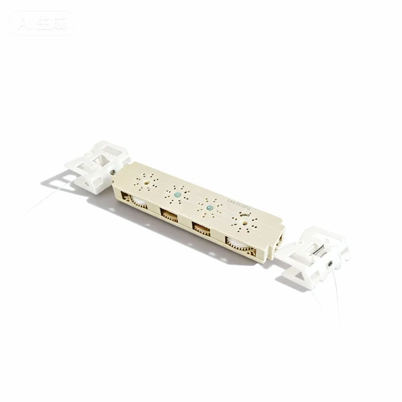
The DOSRON Adjustable Friction Brake Mechanism is a compact control module designed to stabilize blind movement by adding an OEM-tunable damping/holding torque to the drive stack. It helps prevent free-spin, reduces bounce-back, and improves “hand-feel” across roller, zebra, cellular, and horizontal blind platforms where consistent manual control is critical.
|
|
|
What It Solves (In Real Products)
• Jerky motion caused by stick-slip friction or poorly controlled spools.
• Snap-to-top / sudden acceleration when load drops or the spring band crosses a threshold.
• Inconsistent holding where the blind drifts at mid-height or “hunts” near limits.
• Noisy operation from dry contact, chatter, or tolerance stack-up.
This brake is built for OEMs who want a repeatable torque window and a controlled, quiet user experience—at scale.
1) Product Overview
An adjustable friction brake adds controlled resistance into the motion path (shaft, drum, or transmission interface). Instead of relying on “whatever friction happens to exist,” the brake provides a defined torque band that you can tune to your fabric mass, rail geometry, and target feel.
 |
|
2) How the Adjustable Friction Brake Works
2.1 Multi-Point Damping Architecture
- Friction interface: engineered pad/disc contact designed to reduce stick-slip and squeak.
- Preload control: spring or cam preload sets the contact pressure (your main torque lever).
- Geometry control: contact radius and surface finish stabilize torque across temperature and wear.
- Anti-chatter guidance: support features reduce micro-oscillation under intermittent loading.
2.2 OEM Torque Tuning (Practical Bands)
Below is a typical tuning approach used by OEM teams. Exact values depend on your shaft diameter, contact radius, pad material, and target “feel.”
| Application Feel Target | Suggested Holding/Damping Torque Band (Guideline) | Why It Works |
|---|---|---|
| Light residential (smooth, “soft” touch) | 0.25–0.45 N·m | Prevents free-spin without feeling “draggy.” |
| Mid-range (stable stop & hold) | 0.45–0.75 N·m | Reduces drift, improves mid-height stability. |
| Large/heavy builds (strong damping) | 0.75–1.20 N·m | Controls momentum and stop impact under load. |
3) Key Benefits for OEM Brands
- Smoother travel: less flutter, less “grab-release,” better perceived quality.
- Stronger position stability: reduced drift at mid-height and fewer customer complaints.
- Quiet operation: damping reduces chatter; pad choices reduce squeak risk.
- Manufacturing repeatability: defined adjustment method beats “pray the friction is enough.”
- Platform reuse: one brake architecture, multiple SKUs via tuning.
4) Mechanical Interfaces & Compatibility
4.1 Integration Locations
- Shaft-side brake: adds controlled resistance directly to the transmission shaft.
- Drum-side brake: stabilizes spool behavior and reduces overshoot.
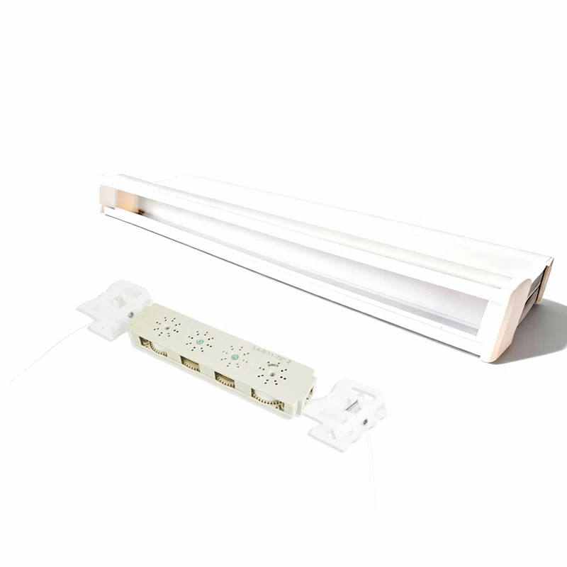
- Module-in-pocket: headrail-ready chassis geometry with anti-rattle locating features.
4.2 Common OEM Interface Options
| Interface | Options | OEM Notes |
|---|---|---|
| Shaft Geometry | Round / D-shaft / Hex / Custom | Match your drive stack to avoid micro-slip and noise. |
| Headrail Pocket | Clip-in / Screw + locator / Left-right variants | Tolerance stack-up control is key to preventing chatter. |
| Drum / Spool | Single / dual drum, radius options | Drum radius shifts required torque—tune together. |
5) Materials & Noise-Control Choices
- Engineering polymers for dimensional stability and low noise (housing, guides).
- Friction media options tuned for consistent torque and reduced squeak risk.
- Metal reinforcement available where higher stiffness is required at mounting points.
- Color matching for visible end components (white/black/gray or project-specific).
6) Technical Specification (OEM-Configurable)
Final specification is defined by your application load band, target feel, and rail constraints.
| Adjustment Method | Preload/cam tuning, shim tuning, or set-screw tuning (project-dependent) |
| Torque Window | OEM-defined; commonly tuned in 0.25–1.20 N·m bands (see Section 2.2) |
| Noise Strategy | Anti-chatter locating features + low stick-slip friction interface |
| Lifecycle Target | Defined by pad + preload design; validation test plan available for your cycle target |
| Operating Temperature | Project-defined (materials selected to maintain stable feel across typical indoor ranges) |
7) OEM Assembly & Installation Notes
- Mount the brake module into the headrail pocket or onto the shaft-side interface.
- Check coaxial alignment and eliminate side-load that could amplify friction variability.
- Set initial torque to your target band and run a full-stroke functional test.
- Verify: no free-spin, no bounce-back, and no squeak under representative load.
- Lock the setting (clip/fastener) and record the torque setting for production repeatability.
 |
|
8) Optional Upgrade Path: Motor-Ready Platforms
If your SKU roadmap includes a future motorized version, we can align interfaces so the mechanical control stack can transition cleanly to a tubular motor solution (tube/headrail constraints permitting).
For teams using DT25-series style tubular motor workflows (pairing, limits, charging), reference the motor user manual here: :contentReference[oaicite:0]{index=0}
FAQ
Q1: Is this brake for lift, tilt, or both?
A: It can be applied wherever controlled resistance is needed—commonly in lift drive stacks (spools/shafts) and in some platforms for tilt stabilization. Integration depends on your architecture.
Q2: What causes squeak in friction brakes?
A: Stick-slip friction, dry contact, and tolerance chatter. Selecting the right friction media and keeping alignment stable are the fastest fixes.
Q3: Will higher torque always feel “more premium”?
A: No. Too much torque feels heavy and can increase wear. “Premium” is a stable torque curve—enough to prevent free-spin, not enough to fight the user.
Q4: Can it compensate for uneven load or poor squareness?
A: It helps stabilize motion, but it can’t fully “mask” mechanical misalignment. If the rail/tube is out of level, friction becomes inconsistent.
Q5: How do you set torque consistently in production?
A: Use a defined adjustment method (preload/cam/shim) and a simple QC torque check on sampling plans—don’t rely on subjective feel alone.
Q6: Does it help with child-safe cordless designs?
A: Indirectly—by improving control and holding stability in internal mechanisms, it supports smoother cordless user experiences. Final compliance must be validated at the full product level.
Q7: What’s the fastest way to start an OEM trial?
A: Share your blind type, load band, rail/tube constraints, and target “feel” (light/mid/heavy). We’ll propose an initial tuning band and interface set.
Q8: Can you match our headrail profile?
A: Yes—pocket geometry, left/right variants, and shaft interfaces can be adapted for your profile.
Field Insight
The fastest way to “upgrade” perceived quality in a manual blind is not adding parts—it’s controlling motion. When your brake torque is defined, stable, and repeatable, customers stop describing the product as “stiff” or “slippery” and start calling it “smooth.” That’s the whole game (and yes, your returns team will thank you).