
What’s the Ideal Spring Torque Curve for Cordless Shades? A Practical OEM Tuning Framework
An engineering tuning framework that turns “hand-feel” into measurable targets—then locks it into spring selection, pre-tension, braking, and production tolerances.
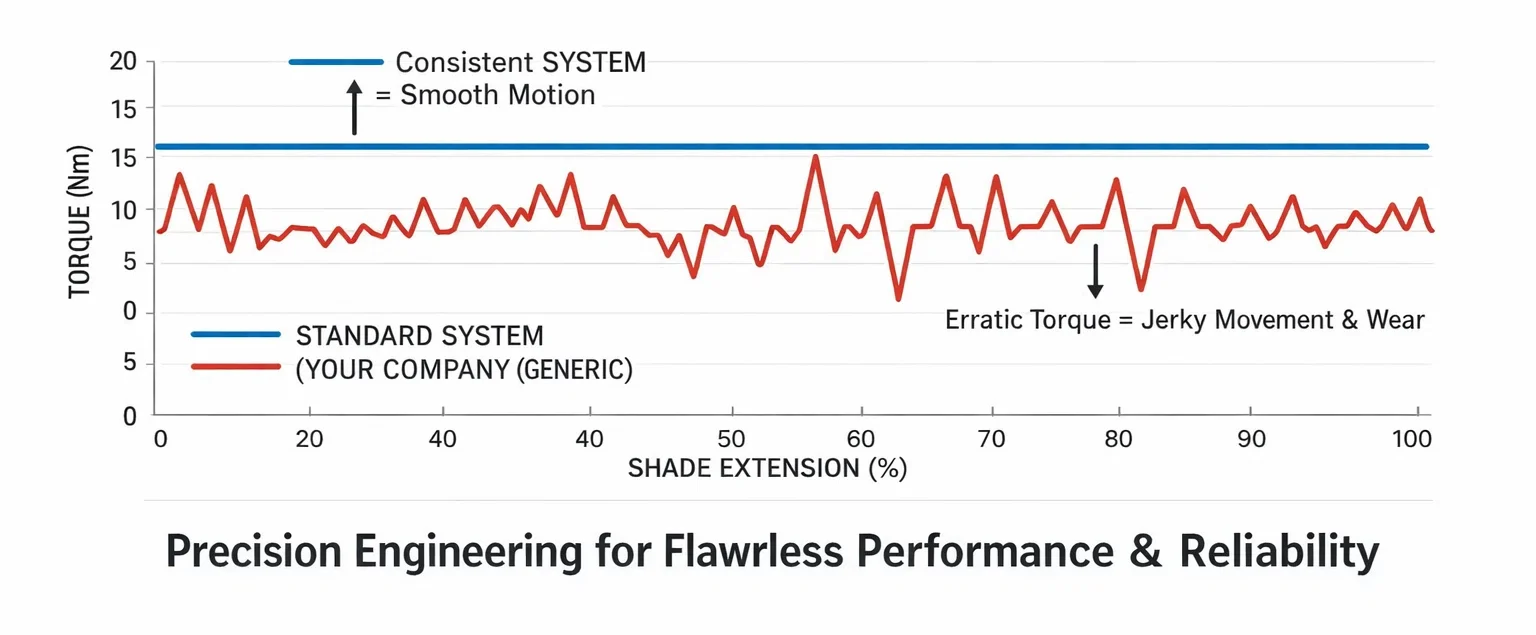
Quick Summary
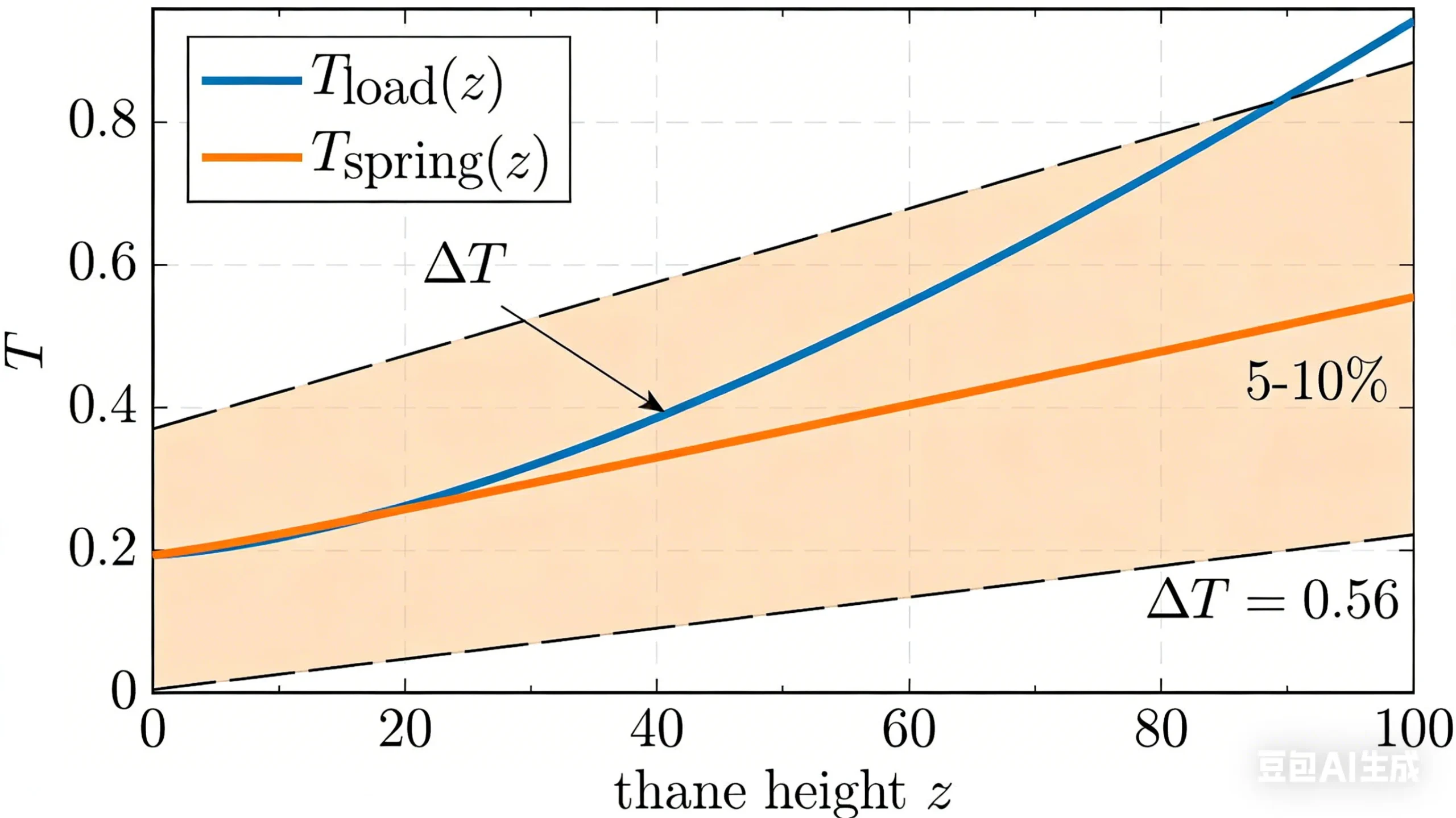
The engineering definition of an ideal torque curve is simple: across the full travel z, keep the net drive margin
ΔT(z)=Tspring(z)-Tload(z)-Tfriction(z)
inside a narrow band, and use braking to lock the lift speed into a controlled window.Practical OEM starting targets (measurable and scalable):
• ΔT band: mid-travel +5% to +10% (vs. Tload), top ≤ +8%, bottom ≥ +3%
• Pull-down operating force: residential 15–30 N; large/heavy fabrics 30–45 N (avoid exceeding 50 N)
• Rise time: full travel 8–15 s; last 200 mm must be visibly decelerated (anti-slam)
• Position drift: at any height, 5 min drift ≤ 5 mm; bounce-back ≤ 10 mm
• Noise peak: ≤ 35 dBA (quiet SKUs: ≤ 32 dBA)
1) Variables & Units: Convert “Feel” into a Calculable Model
1.1 Load Torque
For roller-type cordless shades, load torque is driven by weight and effective wrap radius:
Tload(z)=W × reff(z)
(units: N·m; W in N; r in m).
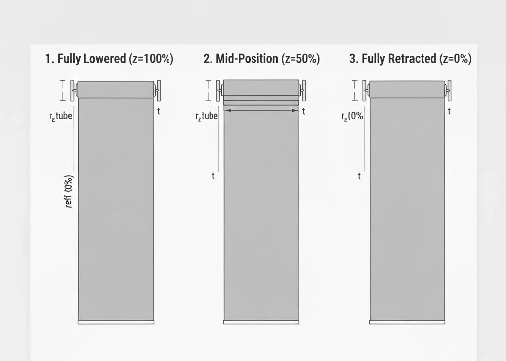
1.2 Effective Wrap Radius reff(z)
reff(z) changes with the number of fabric layers on the tube. This is the root cause of “heavier feel near the top” and “top slam” in poorly tuned systems.
A practical engineering approximation:
reff(z) ≈ rtube + t × n(z)
where t is the fabric equivalent thickness (m) and n(z) is the layer count (changes with height).
- Typical starting radii: Ø38 tube rtube≈0.019 m; Ø32 tube rtube≈0.016 m
- Fabric thickness guide (for estimation): blackout/heavy t≈0.30–0.50 mm; light fabrics t≈0.18–0.28 mm
|
|
1.3 Friction/Assembly Torque Tfriction(z)
Most production scatter comes from Tfriction (bearings/end plugs, misalignment, burrs/flash, brake friction pair).
The goal is not “zero friction” but stable friction. Lower variance makes it possible to hold ΔT inside a narrow band at scale.
2) Acceptance Targets for an “Ideal Torque Curve” (OEM Spec-Ready)
| Item | Recommended Acceptance Target (Baseline) | Repeatable Test Method |
|---|---|---|
| Pull-down operating force Fpull | Residential 15–30 N; large size 30–45 N; max 50 N | Force gauge/spring scale at top/mid/bottom; 3 repeats each, average |
| Rise time trise | Full travel 8–15 s; last 200 mm must decelerate | Time from fully down to fully up; record last-200 mm share |
| Position drift | 5 min ≤ 5 mm (at any height) | Hold at 25% / 50% / 75% and measure drift after 5 min |
| Bounce-back (release jump) | ≤ 10 mm | Stop, release, measure instantaneous upward jump |
| Noise peak | ≤ 35 dBA (quiet SKU: ≤ 32 dBA) | A-weighted at 1 m; record peak during brake action and end-of-rise |
| Cycle life & drift of metrics | ≥ 50,000 cycles; force/time drift ≤ 10% | Re-test Fpull, trise, drift and noise after cycling |
3) Curve Shape Control: A Practical Three-Zone Target
Don’t chase a “perfect continuous curve” in the spec. A more robust approach is a three-zone target:
bottom (stable take-up), mid (consistent feel), top (anti-slam control).
| Travel Zone | ΔT Target (vs. Tload) | Failure Symptom | Primary Tuning Knob |
|---|---|---|---|
| Bottom 0–20% | ≥ +3% | Weak lift / stalls early | Pre-tension (+0.5–1.0 turns micro-adjust) |
| Mid 20–80% | +5% to +10% (narrow band) | Drift / inconsistent feel | Spring stability + friction stability (tolerances/alignment/materials) |
| Top 80–100% | ≤ +8% (with damping) | Top slam / bounce-back / noise peak | Brake torque, end-zone damping, stop/bumper strategy |
4) 5-Step OEM Tuning Procedure (Execution-Ready)
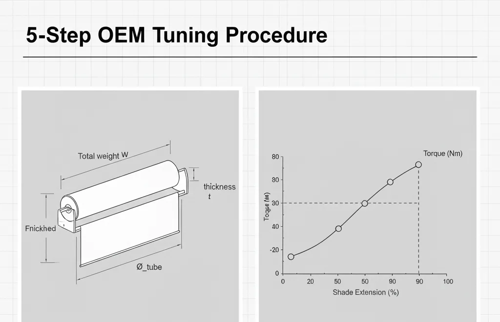
Step 1 — Weight & Geometry Inputs (Minimum Required)
- Total weight W: fabric + bottom rail + end components + any added ballast (N)
- Tube size: Ø32 / Ø38 (to set rtube)
- Fabric thickness t: caliper measurement (mm) for reff estimation
- Finished drop H: drives layer range and speed requirement
Step 2 — Compute 3-Point Torque Targets (Bottom/Mid/Top)
Use three height points: z = 20%, 50%, 90%. Estimate reff for each, then calculate Tload.
Apply zone targets to get:
Tspring,target(z)=Tload(z)+Tfriction(z)+ΔT(z)
If you don’t yet have measured Tfriction, start with an engineering placeholder (e.g., 2–5% of Tload) and replace it with real measured data before releasing production.
 |
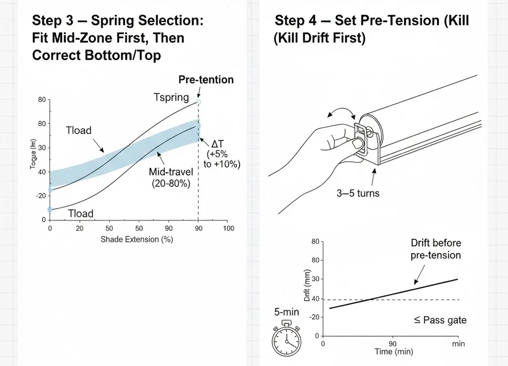
Step 3 — Spring Selection: Fit Mid-Zone First, Then Correct Bottom/Top
- Rule A: mid-travel (20–80%) is where users judge quality—hold ΔT in +5% to +10% there first.
- Rule B: fix bottom shortage with pre-tension; fix top excess with braking/end-zone damping—avoid oversizing the spring as a “quick fix”.
- Differentiation: thick blackout fabrics and heavy rails amplify reff change; top-end speed control becomes a primary requirement, not a “nice-to-have”.
Step 4 — Set Pre-Tension (Kill Drift First)
Pre-tension shifts the baseline ΔT upward to eliminate drift and ensure take-up. A practical starting point:
3–5 turns (bounded by your mechanical design and load band).
Use 0.5-turn increments; after each step, re-test drift and 3-point pull force.
Pass gate: 5-min drift ≤ 5 mm at any height, then move to braking/speed tuning.
 |
Step 5 — Tune Brake/Damping (Control Slam & Noise Peak)
- Speed window: full travel 8–15 s. If < 8 s: increase damping first. If > 15 s: reduce damping or check abnormal friction.
- End-zone control: last 200 mm must slow down; otherwise slam and noise peaks are likely.
- SKU differentiation strategy: keep the same spring platform, and use brake banding to create “quiet residential” vs “commercial heavy-duty” variants without adding new spring SKUs.
5) Symptom → Parameter Mapping (Engineer Actions Only)
| Symptom | Quantified Trigger | Likely Root Cause | Action Order (Fast → Slow) |
|---|---|---|---|
| Position drift | 5 min > 5 mm | ΔT shortage in bottom/mid; or high variance in Tfriction | 1) +0.5 turn pre-tension 2) check coaxiality/misalignment 3) stabilize friction pair (burr/material/lube) |
| Bounce-back | jump > 10 mm | top ΔT too high or weak end-zone braking | 1) increase damping 2) enforce end-zone decel 3) reduce top output (re-band/curve shaping) |
| Pull force too high | Fpull > 45–50 N | ΔT too high; brake too tight; abnormal friction | 1) loosen brake band 2) reduce pre-tension 3) remove interference/offset |
| Fast rise / top slam | trise < 8 s OR no end-zone decel | insufficient damping; top ΔT over limit | 1) increase damping 2) add end-zone control 3) cap top ΔT ≤ +8% |
| Inconsistent feel | 3-point Fpull scatter > ±10% | wrong reff model; tolerance stack-up; unstable friction | 1) re-measure fabric t and layers 2) tighten critical fits 3) stabilize friction surfaces |
6) Production Consistency: Lock the Curve with Tolerances
6.1 Must-Control Items (Incoming & Process QC)
- Coaxiality/offset: end plug and bearing-seat coaxiality must be controlled; otherwise friction variance will consume your ΔT band.
- Brake friction pair stability: material and surface finish must be consistent; batch drift directly changes rise time and noise.
- Pre-tension accuracy: control to ±0.25 turns at assembly; larger scatter creates visible drift and feel split.
- Fabric thickness & bottom-rail mass: small changes amplify top-zone slam risk—especially in blackout/heavy-rail SKUs.
6.2 Minimal DOE Matrix (Baseline)
| Factor | Level 1 | Level 2 | Outputs |
|---|---|---|---|
| Pre-tension turns | baseline -0.5 | baseline +0.5 | drift, 3-point Fpull |
| Brake band | low damping | high damping | trise, end-zone speed, noise peak |
| Fabric thickness/weight | light | heavy | top impact, bounce-back, feel consistency |
FAQ (Engineering)
Q1: Why control a ΔT band instead of only verifying “it goes up and down”?
A: “Up/down” only proves ΔT is positive somewhere. Band control is what simultaneously prevents drift, prevents slam, limits pull force, and stabilizes feel.
Q2: Pre-tension first or brake first?
A: Pre-tension first (drift & take-up), then brake (speed, slam, noise). Reverse order stacks problems instead of isolating them.
Q3: If it slams at the top, why not just downsize the spring?
A: Downsizing often reintroduces drift in the bottom/mid. Top-zone issues should be fixed with end-zone braking/damping and a capped top ΔT.
Q4: How to differentiate SKUs on one spring platform?
A: Two knobs: (1) micro-adjust pre-tension to cover edge loads, (2) brake banding to create “quiet residential” vs “commercial heavy” behavior without new spring SKUs.
Field Insight
In production, the hard part isn’t tuning one perfect sample—it’s keeping 95%+ of units inside the same acceptance window.
Define the torque curve as ΔT zone limits, lock drift with pre-tension, lock speed with braking,
and then write coaxiality, friction-pair stability, and pre-tension accuracy into your tolerance stack and QC plan. That’s how the “curve” actually exists on the line. Contact us for more details:sales2@dosroninc.com