
How to Configure the Best Torque Setup for 2″ High-Profile Headrails
An Engineering Guide to Torque Optimization for Heavy Faux-Wood Blinds — balancing smooth operation, safety, and long-life performance.
 |
 |

Quick Summary
In North America’s heavy 2″ faux-wood blind market, the headrail is not “just a box” — it is a
torque-managed machine. The recurring failures are predictable:
too-heavy pull, rebound, creep/drift, and torque decay after aging.
This guide shows how to match a spring system (energy + torque curve) with a brake system (position-hold + speed control)
so a cordless lift stays smooth for 10,000+ cycles and remains quiet under real-world tolerance stack-up.
Jump to
- 1) Market Reality: Why 2″ High-Profile Systems Are Different
- 2) The Core Math: Understanding Torque Balance
- 3) Spring System Configuration: Getting the Torque Curve Right
- 4) Brake System: Rebound & Creep Control Without Noise
- 5) Engineering Example: 72″ × 72″ Faux-Wood Blind
- 6) Practical Advice for CEOs, Engineers, and Sourcing
- FAQ
- Field Insight
1) Market Reality: Why 2″ High-Profile Systems Are Different
The 2″ high-profile headrail is a dominant architecture for large faux-wood blinds because it has the internal volume
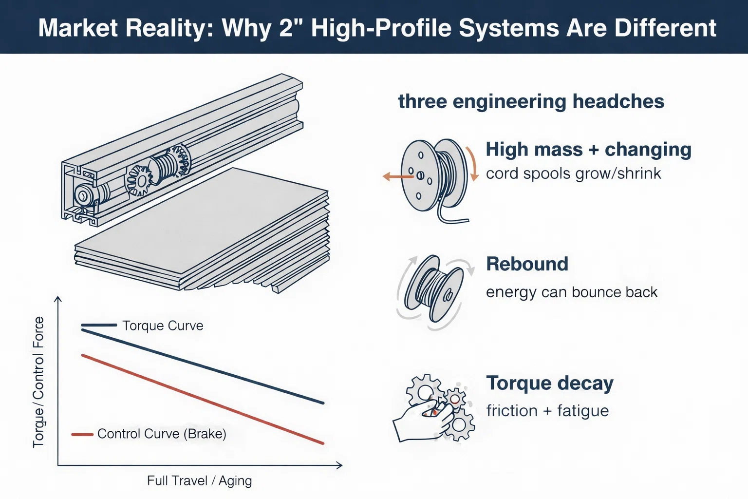
to host a stronger lift stack and handle heavier slat packs. But that same “heavier slat pack” creates three engineering headaches:
- High mass + changing geometry: the effective spool/drum radius changes as cord wraps (even in cordless designs, the lift routing exists internally).
- Rebound: heavy systems store energy; without controlled braking, you get bounce-back at mid positions or slam at end-stops.
- Torque decay over life: fatigue + friction growth (dust, wear, tolerance drift) slowly steals “feel” until the product becomes hard to operate.
In other words: a 2″ system doesn’t fail because the rail is big — it fails when the torque curve and
control curve (brake) don’t stay aligned across the full travel and across aging.
 |
2) The Core Math: Understanding Torque Balance
2.1 Static vs. Dynamic Torque (the “feels fine… until it moves” problem)
Static torque is what you need to start motion and hold position against gravity and internal friction.
Dynamic torque is what you need while the system is moving — and it is affected by changing spool radius,
changing friction, and how fast the brake dissipates energy.
2.2 A practical engineering model (simple enough to use, honest enough to work)
Use this as your first-pass sizing model:
T_required ≈ (W_total × r_effective) × (1 + Friction_Allowance)

Where:
- W_total = total blind weight (slats + bottom rail + internal moving parts)
- r_effective = effective spool/drum radius during operation
 (changes with wrap)
- Friction_Allowance = reserve for bearings, guides, misalignment,
aging (typ. 0.15–0.30)
Why the radius matters: if the drum diameter increases during travel, torque demand increases even if weight stays constant.
Your spring output may do the opposite (torque decreases as it unwinds). That mismatch is where “heavy at the top” or “snatches near the bottom” comes from.
2.3 Design targets that reduce returns (RMA) in the real world
| Metric | Target Band (Typical) | Why it matters |
|---|---|---|
| Operating Force | ~3–5 lbf for heavy systems (application dependent) | Premium feel; avoids “two-hand pull” complaints. |
| Position Hold / Drift | No visible creep at mid-height | Stops the “it won’t stay where I put it” support tickets. |
| Noise | < 40 dB (system-dependent) | High-end brands treat noise like a defect, not a feature. |
| Life | 10,000+ cycles (minimum), ideally higher | Aging stability is the difference between “works at launch” and “works in year 3.” |
3) Spring System Configuration: Getting the Torque Curve Right
3.1 Why linear springs often fail in 2″ high-profile systems
Heavy faux-wood builds tend to have a wider torque spread over travel.
If your spring torque output is too linear (or decays too quickly), you’ll see either:
hard pull at one end or over-lift / snap-back at the other.
The fix is not “bigger spring.” It’s a better torque curve match.
3.2 Variable-torque spring strategy (match the travel, not the brochure)
- Curve matching: tune spring packs so output stays in the same band as the dynamic demand curve across travel.
- Reserve for friction growth: don’t size for Day-1 friction; size for “Day-1 + aging + tolerance drift.”
- Prevent rebound: if spring reserve is too high, the brake must work harder, raising heat/noise/wear.
3.3 Modular spring packs for extra-wide blinds
For wide windows, a single large spring can create packaging problems and inconsistent assembly.
A modular spring pack approach stacks torque predictably while keeping internal layout manufacturable:
- Torque additivity with standardized modules (easier sourcing + faster engineering iterations).
- Assembly stability: less “stuffing” into the headrail, fewer deformation-induced friction points.
- Serviceability: easier to swap one module for tuning instead of redesigning the whole lift core.
3.4 Materials: why Grade 301/316 matters to warranty math
If your brand offers long warranties, fatigue and corrosion resistance are not “materials talk” — they are cost control.
In harsh humidity or coastal projects, higher-grade stainless options (commonly 301/316) reduce force decay and prevent early-life torque drop.
 |
|
4) Brake System: Rebound & Creep Control Without Noise
4.1 Rebound control (the hidden reason heavy blinds feel “cheap”)
Rebound happens when stored energy returns faster than the system can dissipate it.
A brake must do two jobs at once:
hold (static) and stabilize speed (dynamic).
If it only holds, you get jerky motion. If it only slows, you get drift.
4.2 Creep / drift control at mid-height
Creep is usually a torque-balance problem plus micro-slip.
The brake design should maintain consistent friction characteristics across temperature and wear so the blind stays where it’s placed.
4.3 Quiet design (because North American premium buyers can hear your tolerance stack-up)
- Self-lubricating interfaces (e.g., engineered low-friction polymers where appropriate) reduce squeak and stick-slip.
- Controlled contact pressure avoids chatter (intermittent contact) when the headrail isn’t perfectly coaxial.
- Brake + spring synergy: a strong spring without a calibrated brake is basically a “noise generator with ambition.”
5) Engineering Example: 72″ × 72″ Faux-Wood Blind Setup
Below is a practical comparison of what OEMs typically see when they shift from a basic lift stack
to a coordinated spring + brake torque plan in heavy 2″ systems:
| Parameter | Typical Legacy Setup | Integrated Spring + Brake Torque Plan |
|---|---|---|
| Operating Force | 8–10 lbs (feels heavy) | 3–5 lbs (one-hand friendly) |
| Stop Accuracy | Noticeable offset / drift | Stable holding (no visible creep) |
| Noise | High (rattle / snap / chatter) | < 40 dB (quiet, controlled) |
5.1 A repeatable 6-step sizing workflow (OEM-friendly)
- Measure the real load: slats + bottom rail + any moving internal components (don’t guess; heavy blinds punish optimism).
- Map the radius change: spool/drum diameter at bottom vs. top positions (this is where dynamic torque surprises live).
- Set a friction reserve: typically 15–30% based on headrail tolerances, guide surfaces, and expected contamination/aging.
- Select spring output band: aim for an output curve that stays close to demand across travel, not just at one point.
- Calibrate brake behavior: ensure both position-hold and speed stabilization; avoid stick-slip and chatter.
- Validate with life + noise: cycle testing (10,000+ minimum) and noise checks under worst-case assembly tolerances.
6) Practical Advice for CEOs, Engineers, and Sourcing
For CEOs / Owners
- Torque consistency reduces support cost: fewer “hard to lift” and “won’t hold position” complaints.
- Premium feel is measurable: operating force + noise + drift are KPIs, not vibes.
- Platform thinking wins: a standardized torque plan (spring modules + brake cartridge families) scales across SKUs.
For Project / R&D Engineers
- Ask suppliers for torque curve data, not only nominal torque.
- Use test reports + 3D models to shorten iterations and reduce tolerance surprises.
- Validate “quiet” under worst-case coaxiality — that’s where friction noise hides.
For Procurement
- Prefer standardized modules with predictable lead time and batch consistency.
- Audit for material traceability (especially for fatigue-critical spring strip).
- Specify acceptance bands for force decay and noise after cycling.
FAQ
Q1: Why do 2″ faux-wood blinds feel heavier than fabric roller shades?
A: Slat packs are heavier and friction sources are more complex. Also, the effective spool radius can change more during travel, increasing dynamic torque demand.
Q2: If the blind rebounds, should I just increase brake friction?
A: Not alone. Rebound is usually “spring reserve + insufficient dissipation.” If you only crank up brake friction, you may introduce stick-slip noise and heavy pull. Rebalance spring output and then calibrate the brake.
Q3: What causes mid-height creeping (slow drift)?
A: Small torque mismatch plus micro-slip at the brake interface. It often shows up after aging when friction surfaces polish or contamination changes contact behavior.
Q4: What friction reserve should I plan for?
A: A practical starting band is 15–30%, then validate under worst-case assembly tolerances and after cycling. Heavy systems generally benefit from a more conservative reserve.
Q5: Why does the blind get noisy over time?
A: Wear changes contact pressure and friction regime. If the system enters stick-slip or intermittent contact, you’ll hear squeak/chatter. Material choice and controlled interfaces matter a lot.
Q6: Is “stronger spring” a safe shortcut?
A: It’s a tempting shortcut — and a common way to create rebound, slam-to-top, and faster wear. The better approach is a matched torque curve plus a calibrated brake.
Q7: How do I keep performance stable for 10,000+ cycles?
A: Use fatigue-appropriate materials, minimize friction growth points, and verify force/noise after cycling (not just at Day-1).
Q8: Does cordless mean there are zero cords inside?
A: Cordless typically means no external hanging cords or chains. Many architectures still route lift elements internally — and that internal routing is why torque + friction management inside the headrail is so important.
Field Insight
In 2″ high-profile faux-wood blinds, torque optimization is not “one part selection.”
It’s a system alignment: the spring defines the torque curve; the brake defines controllability and feel.
If you want a cordless lift that stays premium after aging, treat these as a matched pair, validate under worst-case tolerances,and test beyond Day-1. (Yes, engineering is basically adulting for machines.)
Need a torque sizing worksheet for your exact width × drop × weight band?
Contact our engineering team to request a calculation sheet or a 2″ system sample kit.